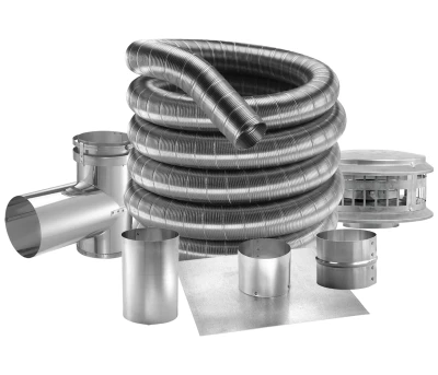
DuraFlex® Aluminum
An economical venting system used for relining masonry chimney for natural gas or liquid propane category I, draft hood equipped appliances, and appliances tested and listed to use Type B Gas Vent for a wide range of applications, including: natural gas fireplaces, gas-fired furnaces, boilers, water heaters, and wall or space heating applications. Protects the masonry chimney from damaging effects of flue product condensation.
Typical Installation
Refer to our Typical Venting Installation drawings to select the appropriate component parts for your installation.
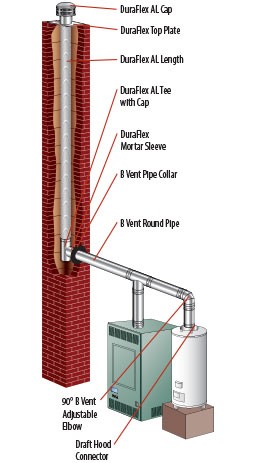
More Typical Installations:
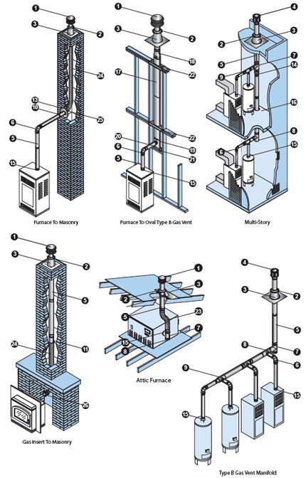
| Installation Key | |
|---|---|
| 1 | DuraCap |
| 2 | Storm Collar |
| 3 | Roof Flashing |
| 4 | High-Wind Cap |
| 5 | Round Pipe |
| 6 | Elbow |
| 7 | Tee |
| 8 | Tee Cap |
| 9 | Increaser Tee |
| 10 | Female Flex Adapter |
| 11 | Male Adapter |
| 12 | Double-Wall Wye |
| 13 | Pipe Collar |
| 14 | Increaser |
| 15 | Draft Hood Connector |
| 16 | Square Firestop Support |
| 17 | Oval Pipe |
| 18 | Oval to Round Adapter |
| 19 | Oval Tee |
| 20 | Oval Tee Cap |
| 21 | Oval Tee Support |
| 22 | Oval Firestop Spacer |
| 23 | DuraConnect II |
| 24 | DuraFlex AL Length |
| 25 | DuraFlex Motar Sleeve |
| 26 | DuraFlex AL Coupling |
How Size and Height Affect Stove Performance
- The amount of heat the vent gases loose as they flow determines how much condensation will occur and how strong the draft will be. To control the heat loses, proper selection of venting materials is of vital importance.
- Double-wall Type B Gas Vent, with an aluminum inner wall and a galvanized steel outer wall, has proven to be the ideal choice in venting materials.
Vent Termination Chart
Using listed Type B Gas Vent caps may terminate in accordance with this table.
| Minimum height | ||
|---|---|---|
| Roof Pitch | Feet | Meters |
| Flat to 7/12 | 1 | 0.30 |
| Over 7/12 to 8/12 | 1.5 | 0.46 |
| Over 8/12 to 9/12 | 2 | 0.61 |
| Over 9/12 to 10/12 | 2.5 | 0.76 |
| Over 10/12 to 11/12 | 3.25 | 0.99 |
| Over 11/12 to 12/12 | 4 | 1.22 |
| Over 12/12 to 14/12 | 5 | 1.52 |
| Over 14/12 to 16/12 | 6 | 1.83 |
| Over 16/12 to 18/12 | 7 | 2.13 |
| Over 18/12 to 20/12 | 7.5 | 2.29 |
| Over 20/12 to 21/12 | 8 | 2.44 |
Gas Vent Specification Chart
| Item | Clearances | Maximum Height | Outer Tube Ø | Materials | Locking Device | UL Listing | ULC Listing |
|---|---|---|---|---|---|---|---|
| Type B Vent Round 3″-8″ | 1 inch to combustibles | 100 feet | 5/8″ larger than ID | Inner – .012″ Aluminum Outer – .018″ Galvanized | DuraLock | MH6357 | CMH1276 |
| Round 10″ to 16″ See note 2 | 1 inch to combustibles | 100 feet | 1″ larger than ID | Inner – .016″ Aluminum Outer – .021″ Galvanized | TwistLock Screws | MH6357 | CMH1276 |
| Round 18″ to 30″ | 1 inch to combustibles | 100 feet | 2″ larger than ID See note 5 | Inner – .020″ Aluminum Outer – .021″ Galvanized | Screws | MH6357 | CMH1276 |
| Oval Type B Vent 4″ and 5″ | 2″ x 4″ & 2″ x 6″ stud wall and 1 inch to combustibles | See Note 3 | 2 1/2″ x 7 1/4″ 3 1/8″ x 10 7/8″ | Inner – .012″ Aluminum Outer – .018″ Galvanized | Button Lock | MH6357 | CMH1276 |
| Oval Type B Vent 6″ | 2″ x 6″ stud wall and 1 inch to combustibles | See Note 3 | 3 1/4″ x 12″ | Inner – .012″ Aluminum Outer – .018″ Galvanized | Button Lock | MH6357 | CMH1276 |
| Type B Vent 3″ to 6″ Round Liner” | 0″/Masonry | 50 feet | 5/8″ larger than ID | Inner – .012″ Aluminum Outer – .018″ Galvanized | DuraLock | MH14420 MH6357 | CMH1407 |
| DuraFlex AL Gas Relining 3″ to 6″ | 0″/Masonry | 50 feet | 1/4″ larger than ID | .010″ Aluminum Flex | Screws DuraLock | MH14420 | — |
| DuraConnect 3″ to 6″ | 1 inch to combustibles | See Note 4 | 1/4″ larger than ID | .010″ Aluminum Flex .018″ Galvalume | DuraLock | MH14089 | — |
| DuraConnect II 3″ to 6″ | 1 inch to combustibles | See Note 4 | 1/4″ larger than ID | .010″ Aluminum Flex .018″ Galvalume | DuraLock | MH14089 | — |
Note:
- Clearance to combustibles is the air space between vent and combustibles.
- Maximum height varies with equipment over 50′, for taller applications refer to SDV sizing handbook (L202). 14″-16″ Pipe require screws.
- When oval is used on wall furnaces, minimum height required from bottom of furnace to cap is 12′, minimum 16″ stud space.
- Limited by sizing tables.
- 18″ pipe OD is one inch larger than ID and 20″ – 30″ OD is 2″ greater than ID